
Picture this: You’re deep into a critical electronics project, deadline looming, when suddenly your soldering iron starts producing cold joints that look like lumpy gray disasters. Your tip has turned black with oxidation, and solder bridges are connecting pins that should never meet. Sound familiar? Every electronics engineer and hobbyist faces these frustrating moments, but the difference between success and failure lies in knowing exactly how to diagnose and fix these issues using your soldering station’s features.
In my years working with electronics, I’ve discovered that most soldering problems follow predictable patterns. The good news? Your modern soldering station is equipped with everything you need to solve these issues — you just need to know which tools to use and when.
Key Takeaways
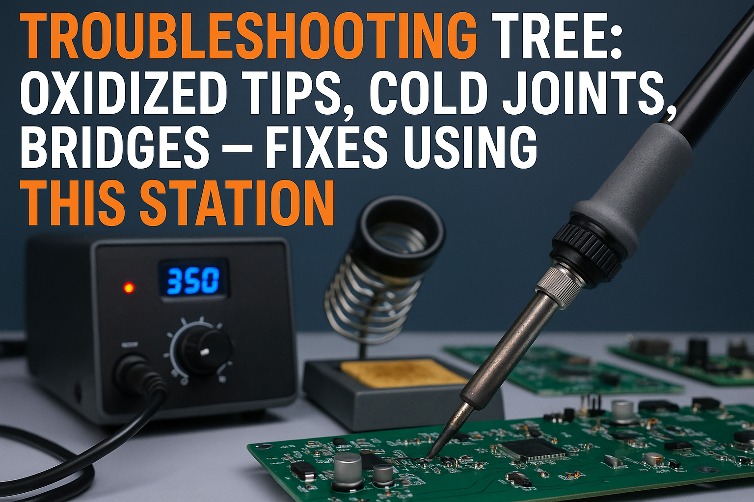
• Oxidized tips can be prevented and reversed using proper temperature control, cleaning techniques, and regular maintenance routines
• Cold joints result from insufficient heat, contamination, or movement during cooling — all fixable with station adjustments
• Solder bridges are eliminated through proper tip selection, temperature settings, and flux application techniques
• Temperature control is your most powerful diagnostic and repair tool for virtually every soldering issue
• Preventive maintenance using your station’s features saves more time than reactive troubleshooting
Understanding Your Soldering Station’s Diagnostic Capabilities
Modern soldering stations aren’t just heating elements — they’re sophisticated diagnostic tools. Before diving into specific problems, let’s understand how your station helps identify issues.
Temperature as Your Primary Diagnostic Tool
Your station’s temperature display tells a story. When you touch your tip to a joint and the temperature drops significantly (more than 50°F), you’re dealing with insufficient thermal mass or too low a base temperature. This insight immediately points to either tip selection or temperature setting issues.
Real-time temperature feedback helps you understand:
- Heat transfer efficiency
- Tip condition and thermal coupling
- Appropriate power settings for different joint sizes
- When your tip needs cleaning or replacement
For optimal performance across different scenarios, understanding why temperature control matters for your soldering station becomes crucial for both diagnosis and prevention.
Station Features That Aid Troubleshooting
Your soldering station includes several features specifically designed for problem-solving:
Digital Temperature Display: Provides real-time feedback on heat transfer and tip condition
Power Adjustment: Allows fine-tuning for different component thermal masses
Sleep Mode: Prevents tip oxidation during breaks
ESD Protection: Eliminates static-related joint failures
Problem 1: Oxidized Tips — The Silent Performance Killer
Oxidized tips are like trying to paint with a dirty brush — the tool becomes the problem. That black, crusty coating on your tip isn’t just cosmetic; it’s a thermal barrier that prevents proper heat transfer and solder wetting.
Identifying Oxidation Levels
Light Oxidation: Slight discoloration, solder still wets with extra flux
Moderate Oxidation: Dark coating, poor solder adhesion, requires cleaning
Severe Oxidation: Black crusty surface, solder balls up and rolls off
The Complete Oxidation Fix Protocol
Step 1: Temperature Assessment
Set your station to 350°C (662°F) — hot enough to activate your cleaning compound but not so hot that you accelerate further oxidation.
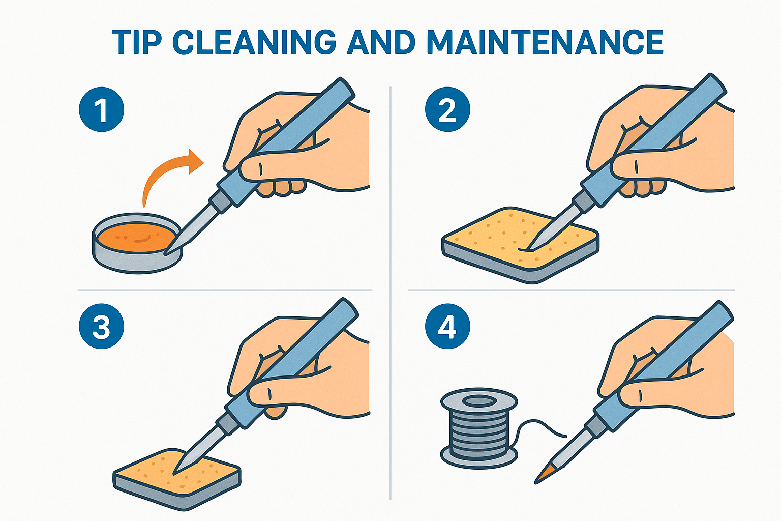
Step 2: Mechanical Cleaning
- Use tip cleaning compound (not abrasives) while tip is hot
- Gently rotate tip in the compound for 5-10 seconds
- Wipe on damp sponge to remove residue
- Immediately tin with fresh solder
Step 3: Re-tinning Process
- Apply rosin-core solder generously to the cleaned tip
- Work the solder around all surfaces
- The tip should appear bright and silvery
- If solder still beads up, repeat cleaning process
Prevention Strategies Using Station Features
Automatic Sleep Mode: Your station’s sleep function reduces tip temperature during idle periods, significantly slowing oxidation. Learn more about maximizing tip life with auto-sleep features.
Proper Temperature Settings: Running your tip 50-100°F hotter than necessary accelerates oxidation exponentially. Use the lowest effective temperature for your work.
Regular Tinning Schedule: Tin your tip every 15-20 joints, not just at the end of sessions.
Problem 2: Cold Joints — The Reliability Destroyer
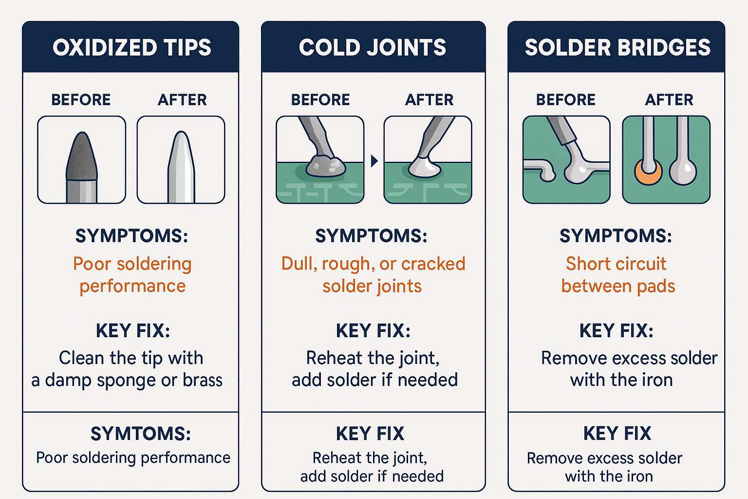
Cold joints are the nemesis of reliable electronics. They look dull, feel mechanically weak, and create intermittent connections that can drive you crazy during troubleshooting.
Recognizing Cold Joint Characteristics
- Dull, grainy appearance instead of shiny finish
- Poor mechanical strength — components move easily
- Incomplete wetting — solder doesn’t flow smoothly around leads
- Crystalline structure visible under magnification
Root Cause Analysis
Cold joints typically result from:
- Insufficient heat reaching the joint
- Contamination on surfaces
- Movement during cooling
- Inadequate flux activation
The Cold Joint Repair Process
Diagnosis Phase
Before heating anything, examine the joint under good lighting or magnification. Look for:
- Flux residue indicating previous attempts
- Component lead oxidation
- PCB pad condition
- Mechanical stress indicators
Repair Execution
Temperature Setting: Increase your station temperature by 25-50°F above normal working temperature. This compensates for heat loss to the existing joint mass.
Pre-heating Strategy:
- Clean the joint with isopropyl alcohol
- Apply fresh flux to all surfaces
- Select appropriate tip size — larger tips for better heat transfer
- Heat all joint elements simultaneously
The key is heating the entire joint — component lead, solder, and PCB pad — to the same temperature simultaneously. Your station’s wattage range and heat delivery capabilities determine how effectively you can accomplish this.
Solder Application:
- Touch solder to the joint, not the tip
- Watch for complete wetting around all surfaces
- Remove solder first, then tip
- Allow cooling without movement
Cold Joint Prevention
Proper Tip Selection: Using the right tip geometry ensures efficient heat transfer. Understanding tip compatibility and the 8 shapes that unlock 90% of your tasks helps prevent cold joints before they occur.
Surface Preparation: Clean leads and pads before soldering
Flux Management: Use appropriate flux for your solder type
Steady Hands: Avoid movement during the critical cooling phase
Problem 3: Solder Bridges — The Short Circuit Creator
Solder bridges between adjacent pins or traces can destroy circuits instantly. They’re particularly problematic with fine-pitch components where pin spacing is minimal.
Bridge Formation Causes
- Excessive solder application
- Poor tip control and technique
- Insufficient flux causing poor solder flow
- Wrong tip geometry for the task
- Temperature too low causing poor solder fluidity
Bridge Removal Techniques
Method 1: Wick and Flux
- Apply fresh flux liberally over the bridged area
- Set station to appropriate temperature for your solder type
- Place desoldering wick over the bridge
- Apply tip pressure and wait for solder to wick up
- Remove wick while hot to prevent sticking
Method 2: Drag Soldering
- Clean tip thoroughly and tin with minimal solder
- Apply flux to the bridged pins
- Drag tip across pins with light downward pressure
- Let surface tension separate the solder
Method 3: Hot Air Rework
For stubborn bridges or dense pin arrays:
- Apply flux generously
- Use hot air to reflow all joints simultaneously
- Allow surface tension to separate connections
- Cool gradually to prevent thermal shock
Bridge Prevention Strategies
Tip Selection: Use chisel tips for drag soldering, conical tips for precision work
Flux Application: Liberal flux use prevents bridges by improving solder flow
Temperature Optimization: Proper temperature presets for lead-free vs leaded solder ensure optimal flow characteristics
Solder Amount: Less is more — you can always add, but removal is harder
Advanced Troubleshooting: When Multiple Problems Combine
Real-world soldering issues rarely occur in isolation. You might encounter oxidized tips creating cold joints, or temperature problems leading to both bridges and poor wetting.
The Systematic Approach
1. Station Calibration Check
Verify your station’s temperature accuracy using a thermocouple or temperature-sensitive solder. Inaccurate temperature readings cascade into multiple problems.
2. Tip Condition Assessment
- Visual inspection for oxidation, wear, or damage
- Thermal response test — how quickly does it melt solder?
- Wetting test — does solder flow smoothly across the tip?
3. Environmental Factors
- Ambient temperature affects heat requirements
- Humidity levels impact flux performance
- Ventilation can cool joints too quickly
Workflow Integration
Successful troubleshooting requires integrating these fixes into your regular workflow. Different personas require different station settings and workflows — hobbyists, repair technicians, and educators each face unique challenges.
Safety Considerations During Troubleshooting
Troubleshooting often involves higher temperatures, longer exposure times, and more aggressive techniques than normal soldering. Safety becomes even more critical.
ESD Protection
Rework and troubleshooting can generate static charges that damage sensitive components. Ensure your ESD safety protocols are active throughout the repair process.
Thermal Management
- Component temperature limits — some parts can’t withstand rework temperatures
- PCB substrate protection — excessive heat can delaminate boards
- Adjacent component shielding — protect nearby parts during repairs
Ergonomic Considerations
Troubleshooting often requires extended periods of detailed work. Proper ergonomics and handpiece grip become crucial for both safety and success.
Tools and Accessories for Effective Troubleshooting
Your soldering station is the centerpiece, but effective troubleshooting requires supporting tools:
Essential Troubleshooting Kit
- Desoldering wick in multiple widths
- Flux pen for precise application
- Tip cleaning compound for oxidation removal
- Magnification for detailed inspection
- Good lighting to see joint quality
- Isopropyl alcohol for cleaning
Station-Specific Accessories
- Multiple tip geometries for different repair scenarios
- Temperature probe for calibration verification
- Tip cleaning station with damp sponge and dry cleaner
When to Seek Professional Help or Replace Components
Sometimes troubleshooting reveals problems beyond simple technique issues:
Component-Level Issues
- Lifted pads from excessive heat or force
- Component damage from thermal stress
- PCB substrate damage from overheating
Station-Level Problems
- Inconsistent temperature control
- Tip heating element failure
- Calibration drift beyond adjustment range
If you’re experiencing persistent issues despite proper technique, it might be time to shop for a new XYTRONIC soldering station to ensure reliable performance.
Maintenance Schedule for Problem Prevention
The best troubleshooting is prevention. Establish a regular maintenance routine:
Daily Maintenance
- Tin tip before and after use
- Clean tip regularly during work
- Check temperature accuracy periodically
Weekly Maintenance
- Deep clean tips with cleaning compound
- Inspect cables for damage
- Verify ESD protection functionality
Monthly Maintenance
- Calibrate temperature settings
- Replace worn tips
- Clean station exterior and ventilation
For comprehensive guidance on building good habits from the start, review our beginner’s guide to soldering safety and ESD basics.
Conclusion
Mastering troubleshooting techniques transforms frustrating soldering problems into manageable challenges. Your soldering station provides all the tools needed to diagnose and fix oxidized tips, cold joints, and solder bridges — the key is understanding how to use these features systematically.
Remember that prevention beats cure every time. Regular maintenance, proper technique, and understanding your station’s capabilities will minimize troubleshooting needs. When problems do arise, approach them methodically: diagnose first, then apply the appropriate fix using your station’s temperature control, tip selection, and timing features.
Next Steps:
- Assess your current setup — check tip condition and station calibration
- Practice these techniques on scrap boards before critical projects
- Establish a maintenance routine to prevent future problems
- Document your settings for different scenarios and component types
The investment in mastering these troubleshooting skills pays dividends in project success, component reliability, and your confidence as an electronics professional. Your soldering station is a precision instrument — treat it as such, and it will serve you reliably for years to come.
For more insights and techniques, explore our complete soldering station blog for additional tips and advanced techniques.