
Picture this: you’re working on a delicate SMD component with tiny pads, and suddenly you need to switch to desoldering a massive ground plane connector. The temperature that worked perfectly for those small pads now feels sluggish against the heavy copper ground. Sound familiar? This temperature and dwell time challenge is one of the most common frustrations I hear from electronics engineers and hobbyists alike. The good news? With the right understanding of thermal dynamics and proper station tuning, you can master this transition seamlessly.
Key Takeaways
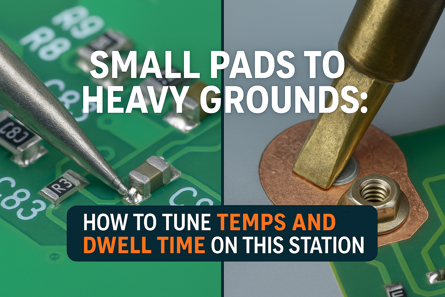
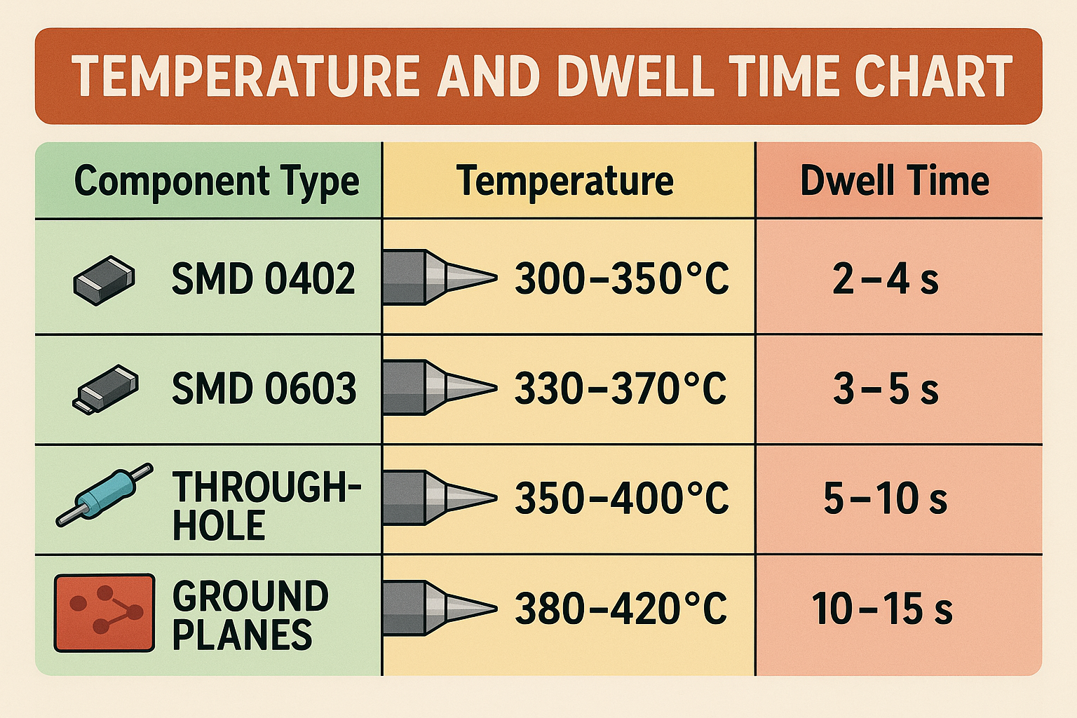
• Temperature scaling: Small pads typically require 300-350°C, while heavy grounds need 380-420°C for efficient heat transfer
• Dwell time optimization: Light components need 2-4 seconds, heavy grounds require 8-15 seconds for proper thermal saturation
• Thermal mass management: Understanding the heat sink effect of ground planes is crucial for successful soldering
• Station setup: Proper tip selection and power settings can reduce the temperature differential needed between applications
• Safety protocols: Higher temperatures and longer dwell times require enhanced ESD safety measures and ventilation
Understanding the Thermal Challenge 🌡️
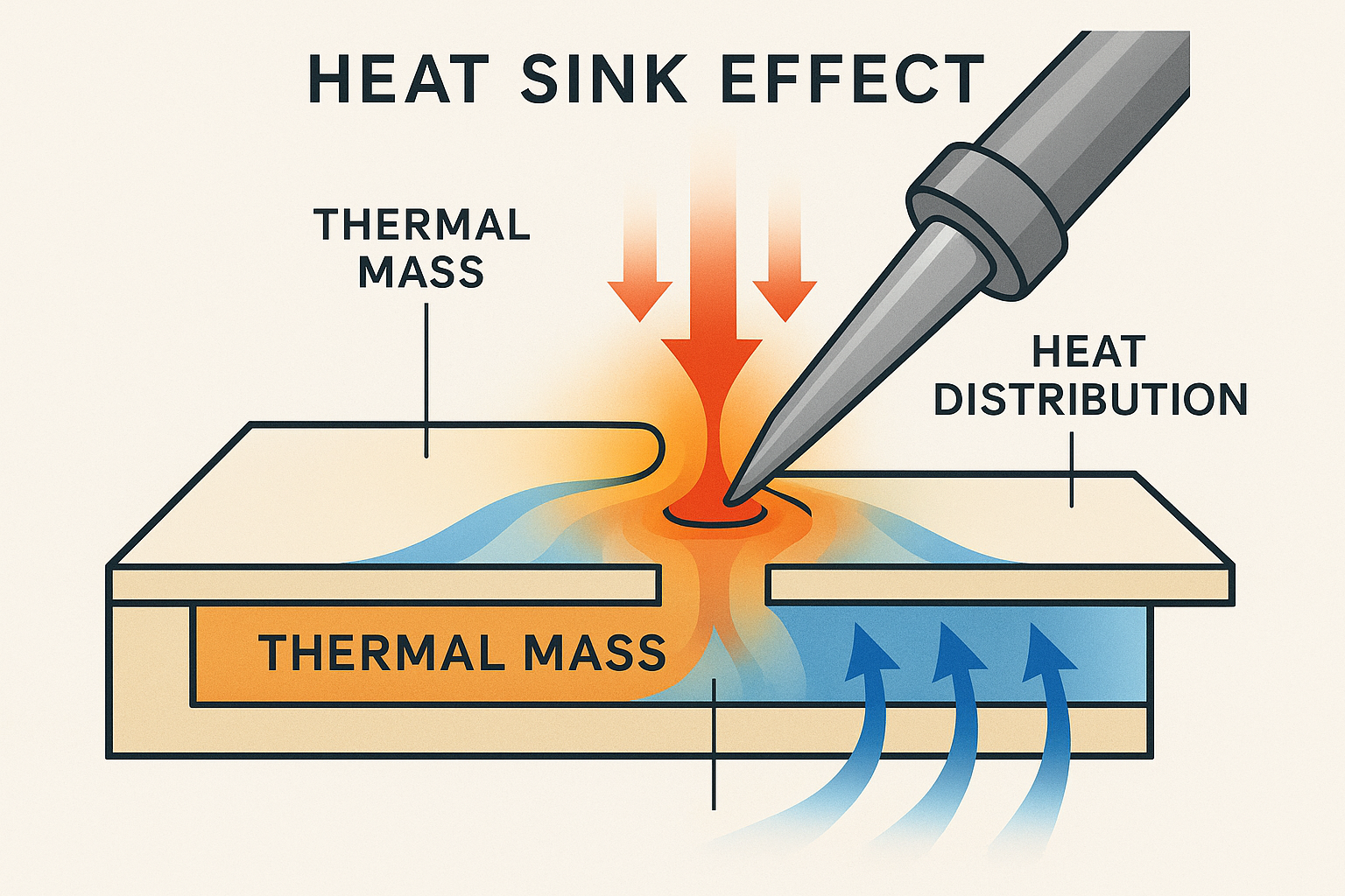
When transitioning from small pads to heavy ground planes, you’re essentially moving between two completely different thermal environments. Small surface-mount pads have minimal thermal mass – they heat up quickly and require relatively low temperatures to reach the melting point of solder. Heavy ground planes, on the other hand, act like massive heat sinks that can absorb enormous amounts of thermal energy without significant temperature rise.
The physics behind this difference lies in thermal conductivity and heat capacity. A small 0402 resistor pad might have a thermal mass 100 times smaller than a large ground plane connector. This means the energy required to bring both to soldering temperature varies dramatically.
The Heat Sink Effect
Ground planes present a unique challenge because they’re designed to dissipate heat efficiently. When you place your soldering iron tip on a heavy ground connection, the heat doesn’t just stay at the joint – it spreads throughout the entire copper plane. This heat sink effect means you need both higher temperatures and longer contact times to achieve proper solder flow.
I’ve found that many engineers underestimate this effect and end up with cold solder joints on ground connections while their small component joints look perfect. The key is understanding that temperature control matters more than ever when dealing with mixed thermal loads.
Temperature Tuning Strategies
Starting Points for Different Applications
| Application Type | Recommended Temperature | Typical Range |
|—————–|————————|—————|
| Small SMD (0402, 0603) | 320°C | 300-340°C |
| Medium SMD (1206, SOIC) | 340°C | 320-360°C |
| Through-hole components | 360°C | 340-380°C |
| Heavy ground planes | 400°C | 380-420°C |
| Large connectors | 420°C | 400-450°C |
These temperatures assume you’re using lead-free solder with a melting point around 217°C. For leaded vs lead-free applications, you can typically reduce these values by 20-30°C.
Progressive Temperature Adjustment
Rather than making dramatic temperature jumps, I recommend a progressive adjustment approach:
- Start conservative: Begin 20°C below your target temperature
- Test and adjust: Make small 10°C increments based on solder flow behavior
- Monitor tip condition: Higher temperatures accelerate tip oxidation
- Document settings: Keep notes on optimal temperatures for specific board types
The beauty of modern stations is their rapid heat-up and recovery capabilities, which makes temperature adjustments quick and efficient.
Dwell Time Optimization ⏱️
Dwell time – the duration your iron tip stays in contact with the joint – is equally critical as temperature. Too short, and you get cold joints. Too long, and you risk component damage or pad lifting.
Calculating Optimal Dwell Times
For small pads, the thermal mass is low enough that 2-4 seconds typically provides adequate heat transfer. The solder should flow within the first 2 seconds, with an additional 1-2 seconds for complete wetting.
Heavy grounds require a completely different approach. The initial contact might take 5-8 seconds just to bring the joint area to soldering temperature, followed by 3-5 seconds for proper solder flow. Total dwell times of 10-15 seconds aren’t uncommon for large ground plane connections.
Visual Indicators for Proper Dwell Time
- Flux activation: You should see flux bubbling within 1-2 seconds
- Solder flow: Molten solder should flow smoothly, not ball up
- Wetting action: Solder should spread evenly across pad and component
- Joint appearance: Finished joint should be shiny and concave
Tip Selection and Its Impact on Performance
The choice of soldering tip dramatically affects both temperature requirements and dwell times. Larger tips with greater thermal mass can maintain temperature better when contacting heavy grounds, reducing the need for extreme temperature settings.
Recommended Tip Configurations
- Small pads: Fine conical tips (0.5-1.0mm) for precision
- Medium components: Chisel tips (2-3mm) for balanced heat transfer
- Heavy grounds: Large chisel or knife tips (4-6mm) for maximum thermal coupling
When choosing tips for your station, consider having multiple tips readily available for different applications. The time saved by using the right tip often outweighs the inconvenience of tip changes.
Station Configuration for Mixed Applications
Power and Recovery Settings
Modern soldering stations offer adjustable power settings that can significantly impact performance on heavy thermal loads. For mixed applications, I recommend:
- High power mode (60-80W) for heavy ground work
- Standard power mode (40-60W) for general component work
- Low power mode (20-40W) for sensitive components
The station’s auto-sleep and shutoff features become especially important when working at higher temperatures for extended periods.
Preheating Considerations
For boards with extensive ground planes, preheating can dramatically reduce the temperature differential needed between small and large joints. A preheating plate set to 80-120°C can:
- Reduce thermal shock to components
- Minimize temperature requirements at the iron
- Improve overall joint quality
- Reduce dwell times across all joint types
Advanced Techniques for Challenging Joints
The Two-Stage Approach
For particularly challenging transitions, I use a two-stage soldering approach:
- Stage 1: Complete all small pad work at moderate temperatures (320-340°C)
- Stage 2: Increase temperature and tackle heavy ground connections (380-420°C)
This method prevents overheating sensitive components while ensuring adequate thermal energy for ground plane joints.
Thermal Profiling
Understanding your board’s thermal profile helps optimize both temperature and dwell time settings. Use a thermal camera or temperature probe to map how heat spreads across your PCB. This information reveals:
- Heat sink locations and severity
- Optimal approach angles for ground joints
- Component thermal sensitivity zones
- Preheating requirements
Safety and Equipment Considerations 🛡️
Working with higher temperatures and longer dwell times introduces additional safety considerations. Proper ventilation becomes critical as flux activation increases with temperature and time. Ensure your workspace has adequate fume extraction.
Component protection is paramount when using extended dwell times. Heat-sensitive components near heavy ground connections may require thermal barriers or heat sinks during soldering.
For those serious about mixed-application soldering, investing in a quality station with precise temperature control and rapid recovery makes a significant difference. Understanding what makes a station different can help you choose the right tool for these demanding applications.
Troubleshooting Common Issues
Cold Joints on Ground Connections
Symptoms: Dull, grainy appearance; poor electrical connection
Solutions:
- Increase temperature by 20-30°C
- Extend dwell time by 3-5 seconds
- Use larger tip for better thermal coupling
- Consider board preheating
Overheated Small Components
Symptoms: Component discoloration; lifted pads; damaged components
Solutions:
- Reduce temperature for small pad work
- Minimize dwell time on sensitive components
- Use temperature profiling approach
- Improve tip selection for better heat control
Inconsistent Results
Symptoms: Some joints perfect, others problematic
Solutions:
- Document successful temperature/time combinations
- Standardize tip selection process
- Implement consistent preheating routine
- Regular station calibration and maintenance
Ergonomic Considerations for Extended Sessions
When working with mixed applications requiring frequent temperature changes and longer dwell times, ergonomics become crucial. Extended contact times mean longer periods of precise hand positioning, which can lead to fatigue and reduced accuracy.
Consider using:
- Adjustable work surfaces to optimize working angles
- Proper lighting to reduce eye strain during longer operations
- Regular breaks to prevent repetitive stress injuries
- Quality handpieces with comfortable grips for extended use
Building Your Optimization Workflow
Developing a systematic approach to temperature and dwell time optimization saves time and improves consistency. Here’s the workflow I’ve refined over years of mixed-application soldering:
Pre-Work Assessment
- Analyze the board: Identify thermal challenges before starting
- Plan the sequence: Group similar thermal requirements together
- Prepare equipment: Set up tips, temperatures, and preheating
- Safety check: Ensure ventilation and ESD protection are adequate
During Work Execution
- Start conservative: Begin with lower temperatures and shorter times
- Adjust incrementally: Make small changes based on joint quality
- Document successes: Note optimal settings for future reference
- Monitor progression: Watch for signs of overheating or underheating
Post-Work Review
- Inspect all joints: Check both small and large connections
- Test functionality: Verify electrical performance
- Update documentation: Record successful parameter combinations
- Equipment maintenance: Clean tips and check calibration
Ready to Master Temperature Control? 🎯
Understanding the relationship between thermal mass, temperature, and dwell time transforms challenging mixed-application soldering from frustrating guesswork into predictable, professional results. The key lies in recognizing that one size doesn’t fit all when it comes to soldering parameters.
Whether you’re working on delicate SMD components or tackling heavy ground plane connections, having a station with precise temperature control and rapid recovery makes all the difference. For those looking to upgrade their capabilities, consider exploring options to shop XYTRONIC soldering stations that offer the precision and reliability needed for demanding mixed-application work.
Conclusion
Mastering the transition from small pads to heavy grounds requires understanding the fundamental physics of heat transfer, systematic approach to parameter optimization, and the right equipment for the job. Temperature scaling from 320°C for small pads to 400°C+ for heavy grounds, combined with dwell time adjustments from 2-4 seconds to 10-15 seconds, provides the foundation for success.
The investment in proper technique and equipment pays dividends in improved joint quality, reduced rework, and increased confidence when tackling challenging boards. Remember that safety considerations become even more critical when working at higher temperatures with extended contact times.
Your next steps:
- Document your current temperature and dwell time settings for different applications
- Experiment with the progressive adjustment approach on practice boards
- Consider upgrading to a station with better thermal recovery if you regularly work with mixed applications
- Develop a systematic workflow that includes pre-work assessment and post-work review
With these techniques and understanding, you’ll find that even the most challenging thermal transitions become manageable, predictable, and professional.